|
PO Box 2087 Forest Park, GA 30298 |
 |
|
Phone: 800 735 0416 email: sales@demico.com |
|
|
|
|
Design and Manufacture of Innovative Electronic Instruments and Controls for the Power and Gas Utilities Since 1978 |
|
WIND BEARING TRANSDUCER |
|||||
|
0 to 540 Degree Scaling |
|||||
 |
|||||
|
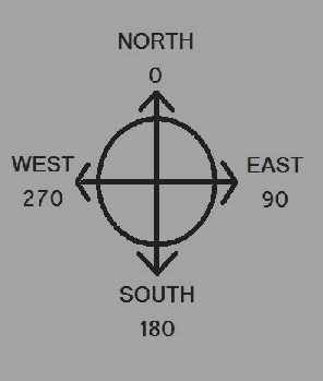
Wind Bearing is usually described by the direction from which the wind is blowing. The eight common compass points, North, South, East, West, North-East, North-West, South-East, and South-West give general directional data, but more precise indications are expressed in the 360 degrees of a circle. As shown above, North is assigned zero degrees, and the degrees increase clockwise toward the east. |
 |
|
540 degree option 1. Calculate: Bearing = (Value/Full Scale)X540+90 2. Compare: Compare Bearing with 360 3. If Bearing is Less Than 360 then Bearing is correct. 4. If Bearing is Greater Than or equal to 360, then subtract 360 from Bearing. |
|||
|
The WB can be ordered with one of two output options. The zero to 540 option is illustrated below. The 540 degree option graph above shows a very complex output curve. Note that there are only 360 degrees denoted on the graph. The 540 degreescomes from the slope of the output curve. The slope is one milliamp per 540 degrees. Note the arrows drawn on the curve which denote the paths for clockwise or counterclockwise movement of the wind vane. Also notice that at 90 and 270 degrees there is a discontinuity, and the path is one way. This pattern is called hysteresis. Once a discontinuity path is traversed, slight movements in either direction do not cause a large change in output. This option prevents large changes in output for small movements in direction, such as can occur in the 360 degree option at North. To effectively use the 540 degree option, the processing computer must be capable ofmaking the following computations and comparisons. 1. Calculate: Bearing = (Value/Full Scale) X 540 + 90 2. Compare: Compare Bearing with 360 3. If Bearing is Less Than 360 then Bearing is correct. 4. If Bearing is Greater Than or equal to 360, then subtract 360 from Bearing. |
|||
|